Skip to content
Bespoke Pot Magnet Design for Oil and Gas Application
By Paul Fears | 14 April 2020
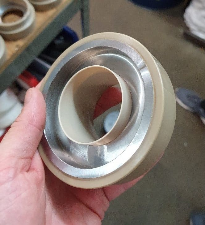
An international Oil and Gas company turned to Bunting when investigating designs for a novel magnetic system to act as a pressure relief valve. The Pot Magnet assembly design requirements were complex with a number of significant technical challenges.
The initial design evaluation identified that the bespoke magnet assembly would be based on a simple Ferrite Pot Magnet. However, the application dictated a highly bespoke design incorporating novel encapsulation methods, down-hole quality steel, and bespoke magnet coatings.
Magnetic Performance
From the customer-defined specifications, including a magnetic pull-force target and a maximum space envelope, Bunting’s engineers considered the design options. Firstly, the team reviewed the magnetic field. A Pot Magnet generates a very localised field through the careful recirculation of magnetic flux from the rear of the magnet to the annuls on the steel pot face. The new design had to ensure that the magnetic flux was not diverted into any magnetically susceptible materials in the surrounding area. This was challenging as one of the key design criteria was to also maximise the size of the Pot Magnet (to generate the highest potential pull force), whilst maintaining a safe distance away from the magnetic steel outer structure of the system.
- Standard Pot Magnets available to purchase online at eMagnets UK
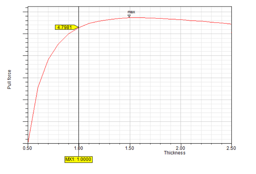
The engineering team assessed the thickness of the Pot Magnet in relation to the diameter. Optimising the relationship between thickness and diameter was difficult as there is a rapid increase in the pull force as the thickness is increased followed by a slow “expensive” wait to the pull force peak. Then, there is a slow drop off in pull force as the magnet gets thicker. This may be counter-intuitive, but the analysis showed that doubling the thickness from 1 to 2mm only increased the pull force by 1%. Yet the cost had doubled. The peak pull force was only 4% above the optimum, yet had a 50% increase in cost.
System Integration
The second stage of the design focused on the magnet outer housing. The outer housing needed to be non-magnetic and meet the stringent down-hole material specifications. When in operation, the strength of the housing would be strong enough to hold the Pot Magnet in position.
After reviewing potential housing materials, the decision was made to use Polyarylethe-retherketone (PEEK). PEEK is a semi-crystalline thermoplastic with excellent mechanical and chemical resistance properties that are retained to high temperatures. The material is commonly used in demanding applications such as for bearings, piston parts and pumps.
Although PEEK was perfectly suited to the application, it can be difficult to work with. Subsequently, Bunting’s engineers contacted an experienced rapid prototyping company and built a bespoke injection moulding tool. This enabled moulding around and behind the Pot Magnet in PEEK, ensuring the magnet assembly would be held in the correct position.
However, the tight tolerances meant that the over-moulding had to be post-processed to generate the thread form used to integrate the magnet assembly into the casing, whilst maintaining the outer diameter concentric to the inner diameter of the casing.
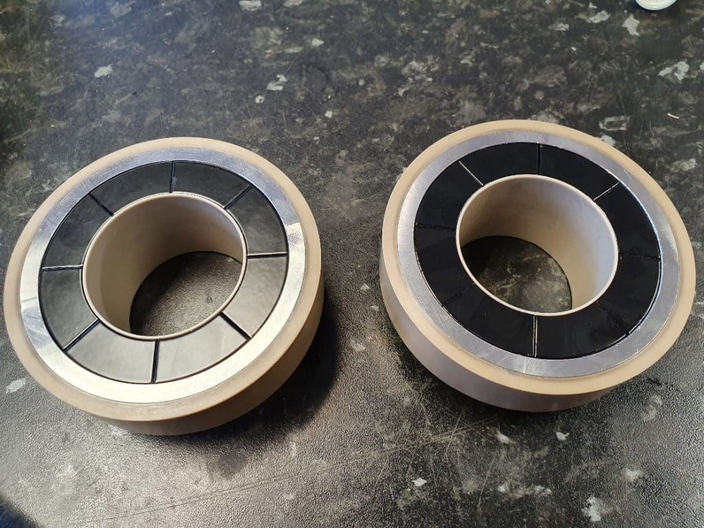
Pot Magnet Assembly and Magnetisation
After determining the optimum magnetic field and down-hole specification and design of the magnet housing, the focus turned to the specification of the magnets.
To prevent damage, the magnets needed a coating. The coating material had to comply with down-hole specifications and, after considering several options, engineers selected the material Nylon 8.
The assembly and coating process determined that the magnets had to remain un-magnetised. One side of each uncharged magnet was coated with a relatively thick layer of Nylon 8 (approx. 0.2mm), whilst the opposite side remained uncoated to ensure good adhesion with the pot housing.
For previous projects, the Bunting team has successfully developed manufacturing processes to build a magnet assembly uncharged and then magnetise post-assembly. In this project, the requisite magnetic force required for the Pot Magnet would have made assembly, whilst magnetised, almost impossible. Any nearby magnetically susceptible materials would have been attracted by the huge pull force. Once on the magnet, any attracted and attached materials would be exceptionally difficult to detach. Assembly of the high-strength Pot Magnet in a magnetised state also posed several safety risks.
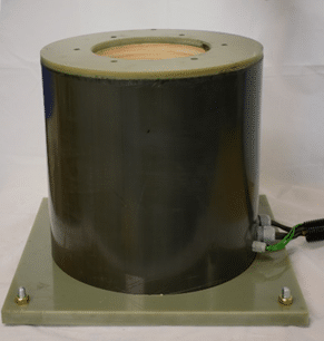
For post-assembly magnetisation, Bunting designed a magnetising fixture and large bespoke magnetising coil. This consumed 100kj of energy per pulse, which was sufficient to ensure magnetisation of the complete magnet assembly (with the Pot Magnet mounted inside the very large magnetic steel casing).
The subsequent engineering challenge focused on controlling the significant forces generated on the component during the magnetisation process. As the magnet assembly was not in the centre, the process of magnetisation would make the casing want to move. To alleviate the problem, the magnet assembly was positioned in the position of lowest energy.
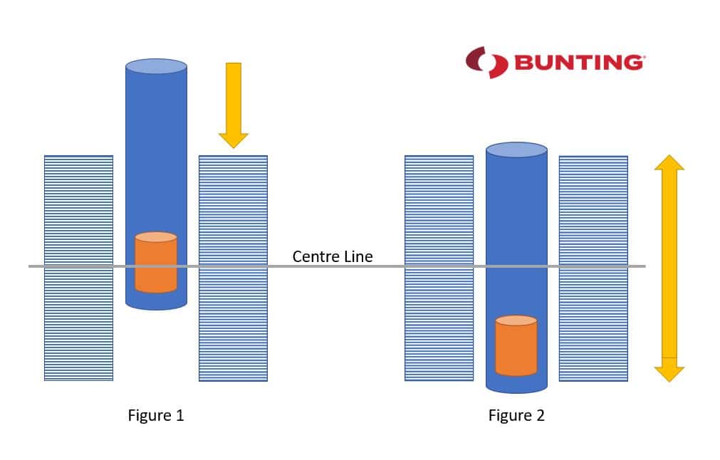
In Figure 1, the centre line of the magnetising coil is lined up with the centre line of the magnet assembly for optimum magnetisation. However, this would generate a downward load on the casing of over 5000N. Also, if the casing had been constrained, the coil would experience the same lifting load.
By designing a coil that would still generate 3 Tesla in the magnet assembly at a location where the casing was in the middle of the coil (as shown in Figure 2) it was possible to nullify all forces and ensure a safe and repeatable magnetising process. This technique required more energy than used in a standard coil, but with 100kj available, it was possible to fully saturate the part.
This processing method was validated by magnetising a single magnet assembly, whilst our specialist magnet inspectors plotted the magnetic field above the surface of the assembly. This procedure was conducted at room temperature and also at 150 degrees. The recorded plot data of the single magnet assembly and the in-situ post-assembly magnetised part were then compared. The results were found to be similar when the effect of the casing was considered and the design verified.
Conclusion
The complex product design process, whilst working closely with the end customer, resulted in the production of a simple Pot Magnet now suitable for an exceptionally demanding application. The successful design and construction were only possible by using key application-specific materials and employing specialist post-assembly magnetising processes.
Bunting design and manufacture a wide range of magnets and magnetic assemblies. Many are bespoke for specific applications. For further information on post-magnetising magnet assemblies, bespoke magnet assemblies or magnet designs, please contact us via:
Phone: +44 (0) 1442 875081
Email: Sales.berkhamsted@buntingmagnetics.com
Via Bunting-eMagnets for online purchase of Magnets and Magnetic Technology